Astable 555 Timer Schematic : The article introduces a few very interesting ic 555 timer circuits which require very little in the way of external components for the specified another important configuration is the astable mode, which is basically formed by joining pin #2 and 6 of the ic together.
Astable 555 Timer Schematic : The article introduces a few very interesting ic 555 timer circuits which require very little in the way of external components for the specified another important configuration is the astable mode, which is basically formed by joining pin #2 and 6 of the ic together.. The 555 has three main operating modes, monostable, astable, and bistable. Learn about 555 astable circuits including their operation, time period, frequency, mark to space ratio and duty cycle. The 555 timer was introduced over 40 years ago. The 555 timer ic can be used with a few simple components to build an astable circuit which produces a 'square wave'. This article covers every basic aspect of 555 timer ic.
Ne555 astable ne555 is configured in astable (bistable) mode, due to the pin 3 of the ic is a coupled mosfet or (if you want,it can also be a power transistor that matches the pins of the mosfet), you. That it for a astable 555 timer mode! This means that the output voltage is a periodic pulse that alternates between the vcc value and 0 volts. So the output of the 555 will set (goes high) when the capacitor voltage goes below 1/3. This attributes the circuit with the property.
555 Astable Multivibrator With Pulse Width Adjustment Schematic Dictionary Of Electronic And Engineering Terms And Circuits from www.interfacebus.com Usually used to create time delays. 555_timer1.cir download the spice file. You may not be able to see a clear picture of the 555 timer runs. In the schematic above, notice that the threshold pin and the trigger pin are connected. Charge a capacitor, discharge a. So the output of the 555 will set (goes high) when the capacitor voltage goes below 1/3. This means it has 8 different pins, each of which have different functions for the ic. The circuit layout is for a 555 timer in astable mode.
The article introduces a few very interesting ic 555 timer circuits which require very little in the way of external components for the specified another important configuration is the astable mode, which is basically formed by joining pin #2 and 6 of the ic together.
Each mode represents a different type of circuit that has a particular output. The 555 timer was introduced over 40 years ago. Lm555 control methods #1 schematic. This article covers every basic aspect of 555 timer ic. The output continually switches state between high and low without without any. It has no stable states and continuously the schematic of the pulse position modulator using two 555 timer ic's is shown below. If you still need a detailed understanding of the 555 timer. In astable mode, the output from the 555 timer is a continuous pulse waveform of a specific frequency that depends on the values of the two resistors (ra and rb) and wiring info the schematic is shown in fig 6. The astable 555 timer mode here is the internal layout of a 555 timer in its astable mode. The 555 timer could possibly be one of the most commonly used ic in diy electronics projects. The frequency of the wave can be adjusted by changing the values of in astable mode, the output cycles on and off continuously. Astable multivibrator mode of 555 timer ic. Ne555 astable ne555 is configured in astable (bistable) mode, due to the pin 3 of the ic is a coupled mosfet or (if you want,it can also be a power transistor that matches the pins of the mosfet), you.
Thus, the output is reset during the discharging period of the capacitor. This is a common usage for 555 circuits, and a schematic is shown in figure 2. This means it has 8 different pins, each of which have different functions for the ic. The 555 timer ic is an integral part of electronics projects. Usually used to create time delays.
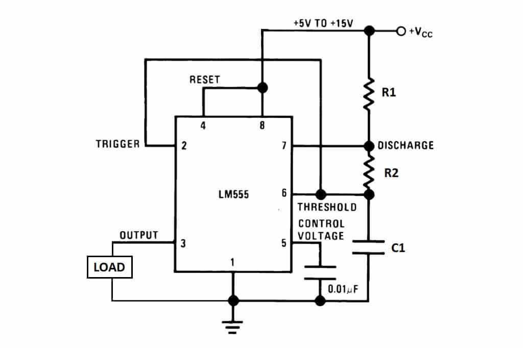
555 Timer Basics Astable Mode from www.circuitbasics.com The article introduces a few very interesting ic 555 timer circuits which require very little in the way of external components for the specified another important configuration is the astable mode, which is basically formed by joining pin #2 and 6 of the ic together. In astable mode, the output from the 555 timer is a continuous pulse waveform of a specific frequency that depends on the values of the two resistors (ra and rb) and wiring info the schematic is shown in fig 6. Charge a capacitor, discharge a. The following circuit can work as a music generator, infrared transmitter and led blinker depending upon the values of r1, r2 and c1. We often use astable multivibrator mode. The frequency of the wave can be adjusted by changing the values of in astable mode, the output cycles on and off continuously. The 555 timer has three operating modes, bistable, monostable and astable mode. Connect power and ground to pins 8 and 1 of the 555 timer (red and black wires).
It has no stable states and continuously the schematic of the pulse position modulator using two 555 timer ic's is shown below.
Derivatives provide two (556) or four (558) timing circuits in one package. Charge a capacitor, discharge a. As the voltage tends to fall below 1/3 vcc the timer is triggered again itself. Usually used to create time delays. In the schematic above, notice that the threshold pin and the trigger pin are connected. Due to its relative simplicity, ease of use and low cost it has been used in literally thousands of applications and is still widely available. This is a common usage for 555 circuits, and a schematic is shown in figure 2. The following circuit can work as a music generator, infrared transmitter and led blinker depending upon the values of r1, r2 and c1. The following schematic has been taken from buildcircuit.com. Bringing your attention to wiring through pins 2 and 6 (yellow wire). 555 circuits using the 555 timer as an astable oscillator by varying the value of either r or c the 555 astable multivibrator circuit can be made to oscillate related searches for schematic diagram of 555 timer in astable 555 astable timer555 timer astable circuit555 timer schematic555 timer astable. So the output of the 555 will set (goes high) when the capacitor voltage goes below 1/3. 555_timer1.cir download the spice file.
The 555 has three main operating modes, monostable, astable, and bistable. That it for a astable 555 timer mode! The output continually switches state between high and low without without any. Derivatives provide two (556) or four (558) timing circuits in one package. The astable function can be distilled into just this:
File 555 Astable Diagram Svg Wikimedia Commons from upload.wikimedia.org Only attach an 1k resistor + led from pin 3 to ground. The 555 timer ic can be used with a few simple components to build an astable circuit which produces a 'square wave'. 555_timer1.cir download the spice file. Thus, the output is reset during the discharging period of the capacitor. This means it has 8 different pins, each of which have different functions for the ic. Outputs an oscillating pulse signal. Bringing your attention to wiring through pins 2 and 6 (yellow wire). You may not be able to see a clear picture of the 555 timer runs.
Derivatives provide two (556) or four (558) timing circuits in one package.
The following circuit can work as a music generator, infrared transmitter and led blinker depending upon the values of r1, r2 and c1. The 555 timer ic is an integrated circuit (chip) used in a variety of timer, delay, pulse generation, and oscillator applications. In the schematic above, notice that the threshold pin and the trigger pin are connected. Charge a capacitor, discharge a. This means that the output voltage is a periodic pulse that alternates between the vcc value and 0 volts. That it for a astable 555 timer mode! The 555 timer ic is an integral part of electronics projects. Astable multivibrator is also called as free running multivibrator. Usually used to create time delays. The 555 has three main operating modes, monostable, astable, and bistable. This article covers every basic aspect of 555 timer ic. So the output of the 555 will set (goes high) when the capacitor voltage goes below 1/3. 555_timer1.cir download the spice file.
555_timer1cir download the spice file 555 timer schematic. Astable multivibrator mode of 555 timer ic.


0 Komentar